Introduction
In this last module, the frequency analysis of a more complex circuit is performed using phasor analysis. The circuit is made up of three resistors, a capacitor, a coil, a voltage source, and a current-controlled current source. The nodal analysis will be used using Kirchhoff's current law (KCL). We will use the phasor notation and the concept of impedance to finish with a lineal system of equations with complex coefficients. Once taken to its matrix form of three equations with three unknowns, Python will be used for the solution and visualization of the answers; it will be graphically verified that the sum of currents at a given node is zero by forming a triangle with the sum of the branch current phasors
Circuital analysis with phasors
It is proposed to solve the following circuit through nodal analysis using Kirchhoff's Law of Currents and solving the system of equations using Python
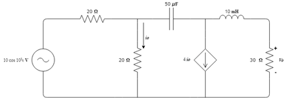
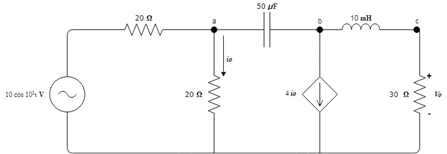
2.1 Circuit nodes are identified.
2.2 Being 3 node voltages the system will consist of 3 linear equations. For the analysis with voltages, we work with the admittances of the circuit; that is, with the inverse of the impedance
2.2.1 For equation 1 of node Va, it is known that it receives two resistance impedances, each one of 20 Ω and a 50 µF capacitor, in addition to sharing with node Vb the 50 µF capacitor, therefore, the final equation of the node is the following: $$ Va ( \frac {1}{10}+ \frac {j}{20})-Vb(\frac {j}{20})=\frac {10} {20}$$ 2.2.2For equation 2 of node Vb, it is known that with node Va it shares a 50µF capacitor, and with node Vc, it shares a 10mH coil, therefore, node Vc would get the previously named capacitor and coil and a source controlled current 4io, where *Io =\frac {Va}{20}* respectively the final equation would be: $$Va ( \frac {1}{5} + \frac {j}{20}) -Vb (\frac {-j}{20})+Vc (\frac {j}{20})=0$$
2.2 For the equation 3 of the node Vc, it is taken into account that with the node Vb it shares the coil of 10mH, and this node receives a resistance of 30Ω and the current that passes through the previously named coil, therefore, the equation of the node i s:
$$Vb (\frac {j}{10}) +Vc (\frac{1}{30} +\frac {j}{10})= 0$$
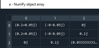
2.3 When obtaining the 3 equations of the system, a 3x3 matrix is made to know the voltages of each node and to interpret the function of the controlled source in a clearer way. (To represent these equations in Python, see in Module 1, point 2.5.2 the explanation of how to do it).
2.4 Then the code is presented with which the above point matrices are plotted and which show whether the circuit is correctly balanced in the current flowing through it and likewise, find the value of the voltages of the three nodes and the current flowing through those three nodes, of course, represented in a phasor and rectangular shape.
2.4.1 For the solution of phasors by Python, the first thing that is done is to call the libraries to work
2.4.2 Following that, the complex admittance matrix is defined thanks to the arrays, as they are called in Python. Once these matrices are declared, linalg will help to find the values of the voltages, where c are these values.
2.4.3 The voltages and currents are worked in polar form; To do this, the real and imaginary part of the voltages is taken and entered in a “for cycle” to be able to find the values in magnitude and phase. It should be borne in mind that Python always delivers the results of the phase in radians; to pass to degrees, it is multiplied by 180 and divided by pi. Subsequently, the real part is called, the imaginary part, the amplitude, which is the absolute value and the phase, once the above is declared, it is requested to show the result already directly in magnitude and phase.
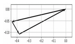
2.4.4 It is necessary to prove that the sum of currents is zero, for that you must use ax = plt.axes () that will help to make the vectors. Since each current is I1, I2 and I3 will be a vector, and these in the join must be a triangle so that you can identify that exercise is good because the current sum is equal to 0. Python shows the three currents and followed this must be passed to its polar form, and the same procedure is done taking the real part, the imaginary part, the absolute value, and the phase (This with the 3 currents).
2.4.5 Since ax is needed to see the vector sum, then for the graph, it will be requested to start at 0.0 to start doing the sum of phasors.
2.4.6 A code running results are as follows
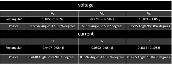
2.4.7 The graph shows that this vector starts at 0.0. The first current runs approximately -0.44 in X and approximately -0.05 in Y, this would be the vector of I1. For the second vector, since it is a vector sum, it begins where vector I1 ends, therefore, on the X-axis it will move approximately 0.05 and on the Y-axis it will move -0.05 and this would be I2, for the last vector on the X-axis it moves approximately 0.4 and on the Y-axis it moves approximately 0.108. Now, it can be seen that the currents in a vector graph if form a triangle therefore the circuit is balanced, that is, the sum of its currents is 0.